
|
|
CE 4905 2003 International Senior Design in the Dominican Republic
|
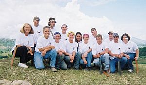 Front Row, left to right, Linda Phillips, Kerry Price, Annette Dickinson, Shauna Ross, Mollie Kauza, Ray Trudgeon, Jesse Mowrer, Angie Martello Back Row, left to right, Andy Luehmann, Tim Martin, Matt Niskanen, Rachel Parini, Brent Rathka, Kevin Pittelko 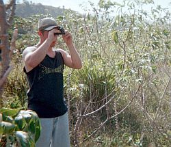 Figure 4: Ray using Abney level |
Introduction Twelve Michigan Tech students
along with Linda Philips, instructor, and Matthew Niskanen, Master's International
graduate of MTU, traveled to the Dominican Republic for senior design
in May of 2003. The students paid tuition, for supplies to construct
a water storage tank, and some other The main objective was to create
an aqueduct that would supply water to the people of a village called
Rancho Viejo. The water is not treated, and the aqueduct simply
moves the water closer to the people. Ten days were spent aiding
in the construction of the water storage tank, surveying While on site students learned
the local building techniques. This knowledge insured that design elements
would be feasible. Working with the Dominicans also provided a unique
forum to discover and appreciate cultural differences. |
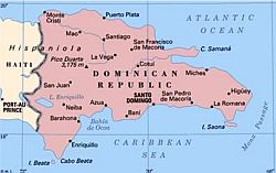
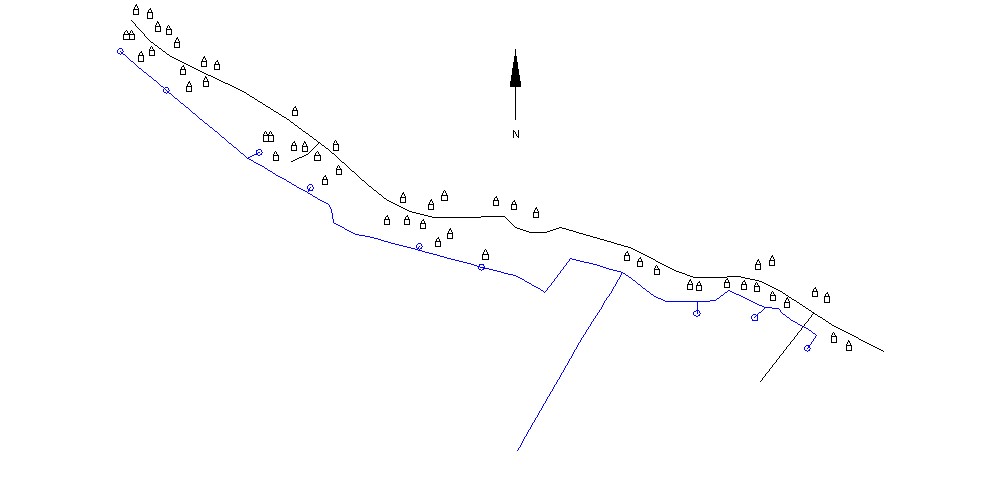 Figure 2: Map of Rancho Viejo and proposed pipelines |
Village
Census
To determine the total water demand of Rancho Viejo a census was conducted.
This census found that the community consisted of 52 households totaling
275 people. The homes are grouped in small clusters spread out along the
road. Using a value of 10 gallons per person per day provided by Peace
Corps of the Dominican Republic a total demand of 2750 gallons per day
was found for the system. |
|
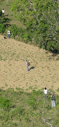 Figure 3: Survey team crossing field |
Survey
and Route Selection
The purpose of the
land survey was to gather data for the design of the water system. This
formed the basis of the system design, pipe sizes, water tank placement,
as well as identifying the need for stronger pipe sections used in gorge
crossings and sections of high pressure. Due to a lack of technology and
availability of modern surveying equipment, Abney Hand Levels were used.
Once the routes were
identified, each group took a stack of hand made stakes, a can of spray
paint and began the survey. The information recorded in a field notebook
included the angles, distances, and compass bearings of the surveyed points.
The main criteria
for route selection included avoiding hard rocky terrain that would impede
installation, and avoiding areas where erosion could easily expose the
pipeline. To meet these criteria routes through fields were often chosen. |
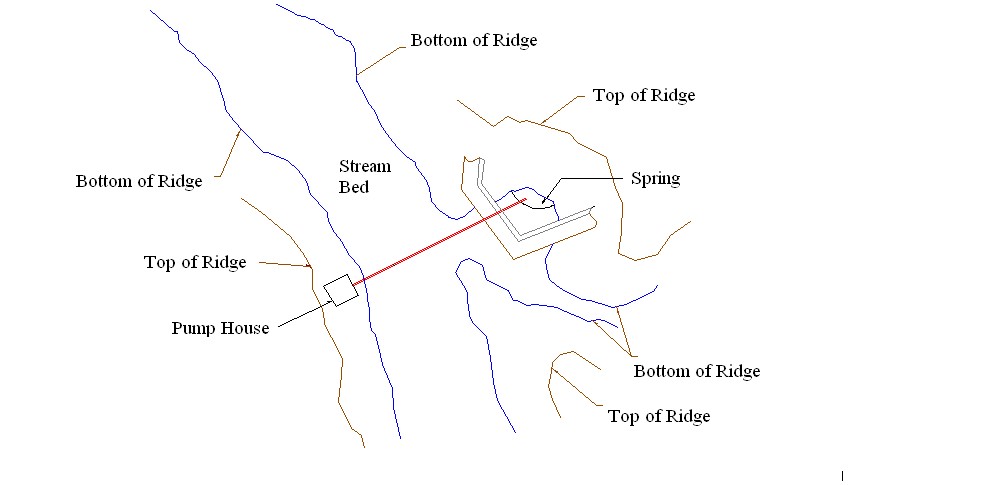 Figure 5: Spring location |
Water Collection
The spring location (Figure 5) in the base of a ravine presented many
problems, such as the close proximity of two streams, that needed to be
addressed in the design process. The water collection basin shown in Figure
6 was designed based on suggestions from former Peace Corps Volunteers
and information found in A Handbook to Gravity Fed Water Systems by Thomas
Hardy. The collection basin has three primary features. First, a reinforced
concrete block wall encompasses the spring acting as a levee to prevent
stream water from contaminating the system. Second, filter cloth and rock
are used to prevent sediment migration into the system. Sediment would
cause damage to the pump and clog pipes. Finally, an impermeable membrane
is used to prevent runoff from the fields above from entering the system. |
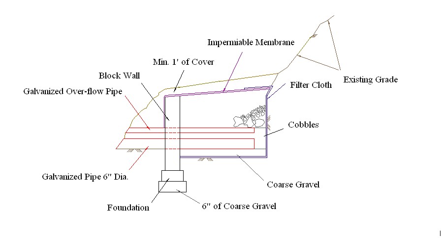 Figure 6: Cross section of Spring Basin |
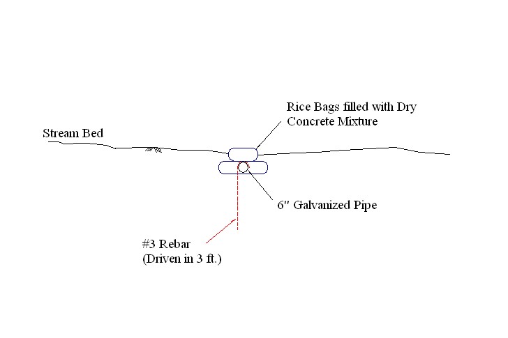 Figure 7: Stream Crossing |
|
Stream Crossing After leaving the collection basin the water must cross the stream to the pump house. A 6� galvanized pipe will be used for the crossing. #3 rebar will be driven into the streambed and tied to the pipe to secure it in place. Finally rice sacks filled with concrete will be placed over the pipe to prevent damage from debris during flooding. This is shown in Figure 7. |
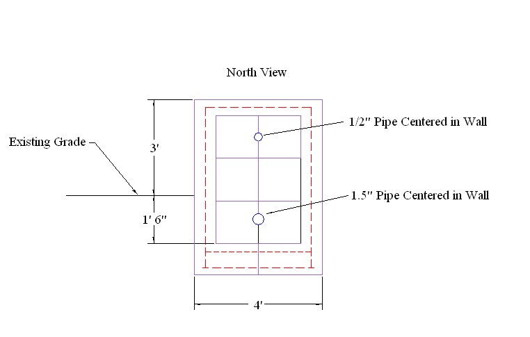 Figure 8: Pump House Cross Section |
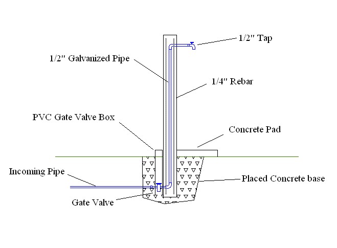 Figure 9: Llave design |
|
| Pump House The pump house is a reinforced concrete block building with cast in place floor and roof (Figure 8). The pump house was located on the village side of the streams to further protect the pump. If the pump were located directly at the spring as originally planned the power supply and pipe connected to the pump would have to cross the stream. If these were wiped out in a flood, sever damage to the pump could occur. The costs of such damage would make repair of the system infeasible. |
Llaves The llaves act as the water faucets for the system. They must be easy to construct, easy to maintain, and have adequate strength and durability. It was determined that a wooden llave would not have sufficient strength and durability, and a stone llave would be difficult to construct due to the Dominicans unfamiliarity with this type of construction. The chosen design (Figure 9) was a precast, reinforced concrete llave that will stand three feet off of the ground. It will be able to be easily constructed and maintained, and also have the strength and durability needed. This llave is also similar to others found in the area, so there is also familiarity with the design |
|
Our system was modeled in a computer program called EPANET. This system allowed us to easily determine the pipe sizes, and pressure at various points along the route. The pipe type was predetermined during the survey; PVC pipe and galvanized iron pipe were the two types of pipe used. EPANET showed us that the llaves along the east side of the tank had low pressure. An alternate route was developed for the east side of the tank that combined the first two llaves, and left the last llave as it was. |
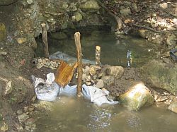
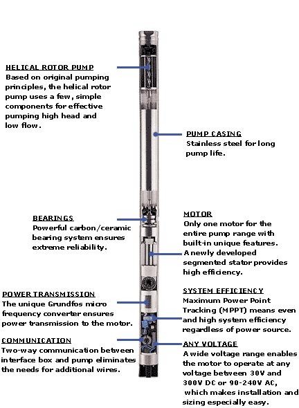
Pump Selection The first step in pump selection was to determine the pump requirements. From the survey it was found that the tank was approximately 150 feet above the spring. To determine the spring flow rate a dam was built around the spring (Figure 10) and the volume time method was used. This process determined the rate to be 6 gal/min. At this rate the spring will supply approximately 1.6 times the demand in 12 hours of pumping. The second step was to choose a power supply. Use of the power grid was dismissed due to the systems unreliability. Many times while in the Dominican Republic the power would go off for no apparent reason, sometimes over a day. The inconsistent and irregular winds in the area eliminated the use of a wind turbine. Due to the location near the equator and consistent 12 hours of daylight year round, solar power was chosen for the system. With the help of Oasis Montana Inc., Grundos 11 SQF-2 submersible helical rotor pump was chosen (Figure 11). This pump is specifically designed for use with solar power and has a high resistance to particles in the water. |
 |
Cost/Schedule
Analysis
Total construction is being broken into two separate phases, a trip in December and a separate section to be completed by the new Peace Corps Volunteer. The trip in December intends to install everything necessary to move water from the spring to the storage tank. This construction will take seven days and cost $8423. The remaining construction will be the installation of the tap stands and distribution pipeline. The installation of the east pipeline will take five days and cost $725. The installation of the west pipeline will take 16 days and cost $1670. The construction and installation of the nine llaves will take 19 days and cost $245. A total of 49 days has been scheduled for completion. There has been an additional $200 added in the total for incidental costs, this brings the project’s total cost estimated to $11,263 Spring Entrapment Basin
$950 |
| Summary
and Conclusion
The final design of the water system for the village of Rancho Viejo is a pump assisted gravity system. The spring will be tapped using the previously discussed spring entrapment basin. This basin harnesses the water and feeds the SQF-2 submersible helical rotor pump. The pump pushes water up a one and a half-inch diameter pipe line at approximately six and a half gallons per minute. This flow will be sufficient to fill the pre-constructed storage tank. From the tank, water enters eastern and western distribution branches. The pipes in these branches range from one and a half inches to a half-inch. The branches are gravity fed from the tank to supply the 9 llaves located throughout the village. The installation of
the pump and the pipe line to the tank will take place in December of
2003. This section of the project will take a total of seven-days
and cost approximately $8,500. The remainder of the project will
be left to be completed after the planned arrival of a new Peace Corps
Volunteer. This portion of the project will cost approximately $2,700
and required 42-days for completion. The final construction of this
project will have brought water to a community of approximately 275-people
many of whom have to currently walk in excess of a mile to obtain their
water. In addition, this project has not only taught a group of
college students how to apply their knowledge of engineering to the design
of a water system, but also how their work can dramatically affect the
lives of others. |
|
| Michigan Technological
University Department of Civil and Environmental Engineering 1400 Townsend Drive Houghton, Michigan, 49931 - 1295, USA Department Phone: 1-906-487-2520 Department Fax: 1-906-487-2943 Department E-mail: cee@mtu.edu
|